
How-To: Finding and Fixing Electrical Gremlins in Your Honda Prelude Racecar
- Roger Maeda

- Aug 1, 2025
- 22 min read
Updated: Aug 3, 2025
One of the unfortunate realities of owning an older car (especially an older racecar) is that they develop mystery electrical gremlins over time. For our StudioVRM.Racing prelude, this included:
An erratic idle that we couldn't fix through parts or the tune
The 10A fuse on the circuit with the ECU kept randomly blowing under load
Random check engine light codes that would flicker at startup and disappear
Alternators burning out earlier than expected
A rare intermittent misfire that would appear once every few events
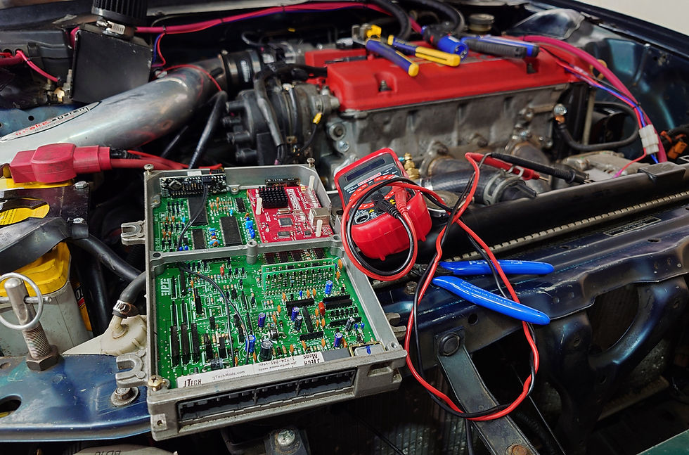
The impact of these mysterious electrical issues came to a head when Fernando at CLM Motorsports discovered that our Prelude's ECU was reporting wildly inconsistent voltage while the engine was running. ECU voltage would drop from almost 14 volts to below 11 volts at load, and dip to under 10 volts at idle - well below what would be considered acceptable performance for a Honda ECU:

Long story short, it was finally time to go through the car's electrical system and eradicate all of the gremlins that had accumulated over the years of hard racing.
Setting the Stage
Like most modern racecars, the StudioVRM.Racing Prelude is a mix of OEM electronics and aftermarket wiring / componentry. At the time of troubleshooting, the Prelude was equipped with:
Jason Waters Tuning engine harness with a direct connection to the ECU
Burton Racing COP Conversion with the Hondarulez COP Board
Honda S300 on a Honda P28 ECU
Internally stock, Naturally Aspirated H22A4 converted to OBD 1 with distributor and sensors
Longacre kill switch wired to disconnect battery ground and alternator field wire when flipped
TL: DR - What Fixed It?
For those of you who are experiencing similar issues, here are the three items that ultimately fixed the issues on our car. Click on these links to skip to those sections and see exactly what we did:
Table of Contents
Step 1 - Easy Checks and Fixes
Step 2 - Easy Wiring Checks
Step 3 - More In-Depth Troubleshooting
Step 4 - Fix or Replace Common Failure Points
Step 5 - Helpful Add-ons
Recommended Tools

Although you need very few tools to start troubleshooting electrical issues, we recommend having the following on-hand when troubleshooting intermittent issues:
A good quality multimeter with an easy-to-read display
A slim LED work light that can fit into tight spaces
A pair of flush cutters
3M Super 33+ or Super 88 Electrical Tape
A self-adjusting wire stripper
A ratcheting crimper for automotive connectors
A box of assorted heat shrink butt connectors and heat shrink ring terminals
A lighter, small heat gun, or a mini torch to seal heat shrink
We at StudioVRM seem to have a fair few Klein and Irwin tools in our electrical kit alongside our collection of Tyco Electronics (TE connectivity) and cheaper TICONN brand crimp-on connectors. But the reality is that most hardware store brand tools and connectors work just fine. You can get a lot for very little money these days, and we strongly encourage you to take advantage of cheap, reliable tools.
That said, we do recommend that you avoid the cheap digital multimeters on Amazon. Many of the cheap ones have accuracy problems and burn out. If budget is a concern, Gardner Bender makes a very affordable analog multimeter that tested spot-on with the Fluke multimeter that we only use for sensitive electronics.
We also recommend that you avoid the cheaper self-soldering butt connectors (the no-crimp kind) as well. They are difficult to install in tight spaces and the outer sleeves of the cheaper ones tend to stretch when heated, compromising the strength of the connection.
Step 1 - Easy Checks and Fixes
Check your voltage from the ECU
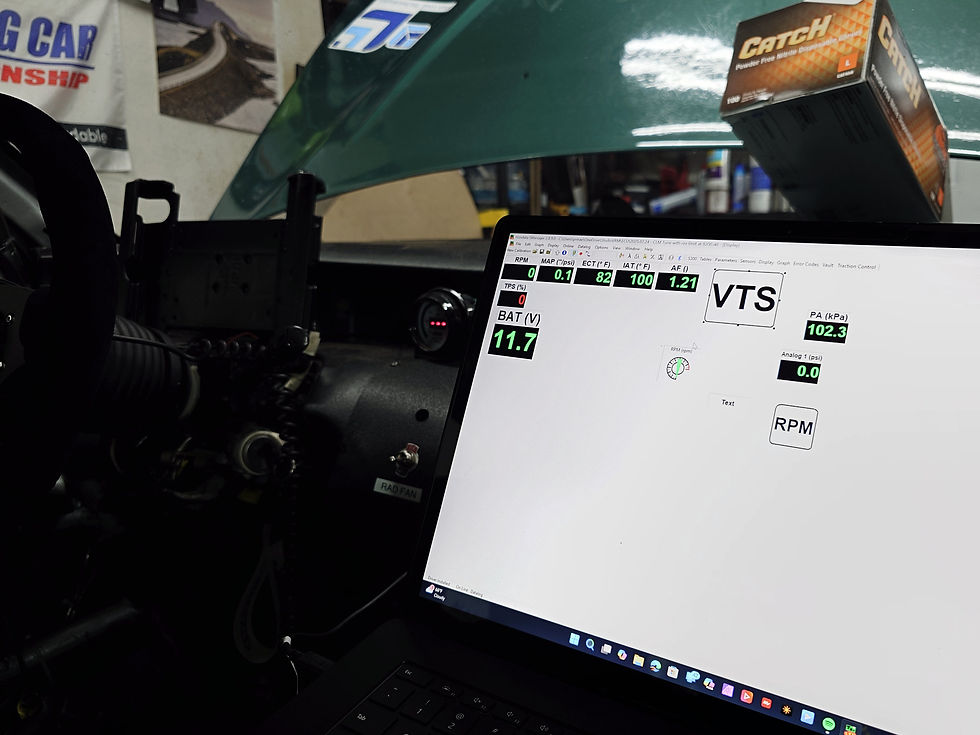
This step was already done for us by Fernando at CLM Motorsports, and it is an important one to note. Modern ECUs, especially standalones, will give you a better picture of what's actually going on in your electrical system than all but the most expensive digital multimeters out there.
The reason is that voltage readings are actually an averaged measurement of voltage over time. What appears to be a steady 12.0 volt signal, for example, is typically a jagged waveform of voltages that averages out to 12.0 volts over a period of time - typically 0.25 seconds (4hz) for a good multimeter to 1 second (1hz) for a cheap one.
ECUs, however, datalog at much higher refresh rates - once every 0.1 seconds (10hz) for the Hondata S300 v2, for example. This will let you see "invisible" electrical problems that you will never see with a handheld multimeter. If you have an ECU that allows you to log and display voltage, we strongly recommend that you use that feature first to see what your car is actually seeing in its electrical system.
It is also possible to detect these issues using a mini handheld oscilloscope. If you do have access to one, we recommend setting the window to about 10hz to start for automotive troubleshooting.
Clean, Replace, and Treat Your Grounds
The type of pulsing, intermittent voltage drops that we saw on the Hondata datalogs
"Clean your grounds" is still sound and important advice for all cars, both new and old. The difference is that, due to age, the grounding cables on many Preludes have corroded to the point where cleaning off the ends will no longer solve grounding issues.
We recommend replacing these big ground wires in your engine bay with new cables:
Engine block to chassis
Negative terminal of the Battery to the starter / transmission
Negative terminal of the Battery to chassis
We used 2 AWG copper welding lead to make new cables for these grounding points, using copper 2 AWG lugs from the local hardware store, this affordable hydraulic crimping tool, and our secondhand Klein cable cutter to get them to the exact length that we needed. Although this does involve buying a few tools and doing some hands-on work, you will get better results (and your grounding cables will last significantly longer) than if you bought an off-the-shelf grounding kit that uses thinner or, copper-coated aluminum wires.

We also recommend disconnecting and sanding all of the wiring harness grounds that you can see in your engine bay (as well as the points that they mount to on the chassis with 320 grit sandpaper. We also recommend replacing any rusty nuts and bolts that might be holding these grounds in place.
Finally, we coated the ends of all of our grounds with an electrical cleaner / protector before reinstalling them. This not only protects the ends from future corrosion, but it also prevents water from migrating up under the insulation of the wire. Steel Camel Thread 'N Post continues to be our favorite for these purposes, but DeoxIT D100L is also a good alternative for those of us who are not planning to do these jobs often.
Ground Your Alternator
This one is important, especially for those of us with painted engine blocks / brackets. If you are having electrical issues, one of the first things on your to-do list should be to remove your alternator, remove the alternator bracket, and sand any paint or rust off of the surfaces between the alternator, alternator bracket, and engine block.

The reason is that our alternators rely on a body ground, meaning that they need a solid metal connection from their casings to the engine block in order for them to work properly. If there is any paint or rust between the alternator and the engine block, this can cause the alternator to produce erratic power and even burn themselves out prematurely.
One way to test whether this is a problem is to make a short grounding wire and connect one of the grounding points on your chassis to one of the small M6 sized nuts / studs on the alternator. If adding this ground wire fixes or improves your car's issues, your alternator bracket needs to be sanded.
Caution: Coil on Plug Conversion Users - Check the Location of Your Grounds
This one is for those of us running Coil on Plug conversions, such as the one offered by Hondata, HondaRulez, or Apollo Tuning. Double check the ground for your ignition coils and ensure that in the location specified by the manufacturer. This is worth noting because, in many cases, this location is NOT the commonly used point on the Thermostat housing.

Many COP kit manufacturers recommend that you ground the ignition coils to one of the bolts for the distributor body to prevent electrical noise from the ignition coils from causing issues with the sensors and ECU. They also recommend that it is the only thing grounded to that location - do not stack other grounds on top of this point.
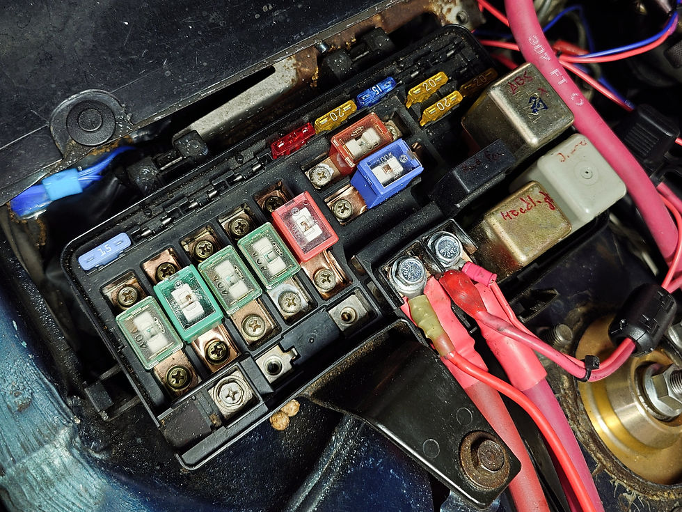
Check Your Fuses
Before you begin digging into the wiring, we recommend checking all of the fuses in your under-hood and under-dash fuse boxes with a multimeter. With the ignition off, set the multimeter to check resistance, and check each fuse by putting the leads against the two metal terminals at the top of the fuse.
Standard automotive fuses should read 0 Ohms (or very close to it) across the leads. If any of your fuses read more than that, have no continuity, or are visibly corroded or damaged, replace it. Write down which fuses you replaced, so you know which circuits to check further down this list.
If you see any corrosion on the fuse box itself, clean the contact points with electrical contact cleaner, Steel Camel, or D100L to ensure a good connection.
Zip Tie Problematic Connectors

Some of the electrical connectors in our cars are notorious for coming loose and causing intermittent issues. These include:
Throttle Position Sensor Connector
Adapter clips for non-OEM (e.g. Bosch) fuel injectors
Connectors for the distributor
We recommend inspecting, cleaning, then zip-typing these connections together with thin cable ties, so they won't vibrate apart and cause intermittent issues.
Step 2 - Easy Wiring Checks
Run the car without the Alternator
At this point in their lifetimes, most Honda Preludes are running rebuilt or aftermarket alternators. Our car is no exception. And while remanufactured alternators are very affordable, many of them have sloppy windings or minor internal issues that can cause intermittent electrical issues.
Because of this, it's often worthwhile to try running the car with the field wire (the 4-wire plug) to the alternator disconnected. Although the base voltage of the system will be lower (under 12v) as you are running solely on battery power, this can sometimes cause the random electrical gremlins and issues to disappear. If this fixes your electrical gremlins, it will be worth trying another alternator.
Run the car with a different Battery (or without a battery)
Conversely, it is also worth trying to run your car with a different battery, or even without the battery.
In addition to its main function of storing enough energy to start the car, car batteries act like capacitors, absorbing and damping out the sudden voltage spikes and dips produced by your car's electrical system. A battery with internal issues won't do this and can allow voltage spikes on one electrical component to affect every other component in the car.
We recommend swapping to another known good lead acid or AGM battery (even if it doesn't quite fit in the same space) or by connecting a battery pack to the battery terminals, then starting the car. In a pinch, you can also (carefully!) remove the positive battery cable (and cover the ends of the cables and the terminals with an insulating material) while the car is running. Modern Hondas will run without a 12v battery, as long as they have a healthy alternator providing power to the engine.
If your mystery electrical gremlins seem to disappear, or you see more consistent voltage when running the car with a different battery, we recommend simply replacing it, even if it starts the car just fine.
Check for Breaks and Shorts in the Wiring
Breaks and shorts in your wiring can be notoriously difficult to find, as there are very few (affordable) tools out there that can accurately locate a broken wire or a short inside an automotive wiring harness.
Fortunately, a visual inspection of the wiring harnesses and the connectors is often enough to locate a shorted wire. We recommend shining a powerful, low-profile LED light right onto the wiring loom and following it from the fuse box to each of the connectors in the engine bay. A slim LED bar light like this Astro 90SL (our new favorite LED light) is a huge help with this, as you can push it into small spaces like those in the back of the engine bay or under your dashboard. Alternatively, you can take an LED headband (also one of our shop favorites), fold it in half, and shove it into tight spaces to get a good look at the wiring in tight spaces.

Look for:
Any exposed metal wire where the insulation has worn through
Any signs of corrosion or blue calcification forming outside the wiring loom in the middle of a run of wire
Any kinked wires or sharp bends in wires, especially those close to the connectors in the engine bay
Any wiring connectors, splices, or soldered points in the middle of the wiring, especially wire splice connectors / t-taps / vampire taps
The pass-through holes in the firewall where the engine harness goes inside the car (this is a common place for intermittent shorts in Honda wiring harnesses)
Any wiring that runs close to the ground (crawl under the car and look from underneath if you have to)
Any parts of the chassis where the harness is screwed or bolted to the chassis - sometimes, the insulation will rub through on the bolt and the wire will short via the fastener (surprisingly common in race and track cars)
This is also a good time to carefully unplug each connector as you inspect it and look inside. Make sure there is no corrosion inside, and that none of the pins are loose. Use contact cleaner or a soft, non-metallic brush to brush out any corrosion, and push the wiring for loose pins in from the back of the connector to see if they will click back in.
If one of the pins in the connector won't lock, the connector itself is broken / looks suspect, or if you suspect a wiring issue inside the connector, consider re-pinning or replacing the entire connector. Most OEM Honda connectors are available, either as kits or as pre-assembled pigtails, from a variety of vendors. The cost of replacement is so low that it is often worth replacing an entire connector instead of trying to troubleshoot it.
Finally, if you locate any breaks or exposed wiring inside the harness, cut the bundling tape, wiring loom, and zip ties from the area, and inspect all of the other wires nearby to ensure that there are no other breaks or cuts. We use a seam ripper and thread snips from a sewing kit to cut into bundling tape and wiring looms without damaging the insulation of the wires inside. Remember to stick the side with the red ball inside the loom to prevent the sharp end from poking through one of the other wires.
If your break or short is caused by a wire that has rubbed through its insulation and the wire itself looks to be in good shape (common in our cars), you can often get away by sealing the break with liquid electrical tape. We recommend using one of the bright colors, such as green, red, or white so you can find the repair location later. We also recommend wrapping the area in durable plastic split wire loom to prevent it from rubbing through again. They may not be the most attractive form of insulation, but they provide excellent abrasion protection and are easy to install in situ.
Step 3 - More In-Depth Troubleshooting
Get the Wiring Diagrams. Rely on them.
Good wiring diagrams are your lifeline when it comes to mystery electrical issues. Yes, they can be intimidating to look at, but remember - all you need from them is to figure out which wires are connected to what (and which circuits share power and ground). Focus on the circuits that are giving you problems, and ignore everything else.
While the PDF versions of the Honda Prelude Factory Service Manual is available from multiple sources online, we recommend buying a paper manual or printing the pages from the Electrical section for easier viewing. The wiring diagrams in the factory service manual span several pages and are much easier to read when printed on paper. Plus you can write on the paper copies in pencil or highlighter.
Bishko reprints of the OEM Honda manuals are available on Summit Racing. Aside from some oddly proportioned images (due to the fact that the original manual was printed on A4 instead of Letter sized paper), they are perfect replicas of the original OEM Honda manuals. We strongly recommend having a copy around, even if it's just for the wiring diagrams.
Do not trust the wiring diagrams from Hayes, Chilton, or other third party manuals. They are well-known for uncorrected mistakes in their wiring diagrams. AllData is the one exception. They are great, if you can afford a subscription.
Use the Troubleshooting Flowcharts in the EM section of the Factory Service Manual

It turns out that the troubleshooting flowcharts in the Factory Service Manual still apply, even if you have an aftermarket engine harness. If you have an idea of where some of your gremlins might be coming from (e.g. the ignition system), follow the steps in these diagrams first. They are very well-written, are easy to follow, and will save you a ton of time and frustration.
Isolate the Problem Circuit by Pulling Fuses
Just like in most new cars, many critical and non-critical electrical components in our Honda Preludes share their power and ground connections with other components. It can often help to temporarily pull the fuses for any non-critical or unrelated circuits to help isolate a problem.
If pulling the fuse for a non-critical component such as the horn or the interior lights improves how the car runs, check the wiring diagram and see if they share a common ground or power source with any critical components (especially those related to your injectors, ECU, or ignition system).
If you have a race car or a dedicated track car that never sees street use, we recommend pulling the fuse for unused circuits entirely, then using a dab of dielectric grease to protect the exposed terminals in the fuse box. This will minimize the chances that a problem in a noncritical circuit will cause issues with critical components in the future.
Replace your Battery Cable and Alternator Cable
This would have been completely unnecessary 10 years ago, unless you lived in a very rust-prone climate. Unfortunately, the wiring on most cars built in the 90s and the early 2000s are now so weather-worn that even the battery and alternator cables have started to corrode inside the insulation.
If you have noticed any calcification or white powder forming at the ends of your positive battery terminal or either of the 12v positive power connections in your underhood fuse box, we recommend replacing the thick cables that connect to your battery and alternator.

We used the same 2 AWG copper welder cables that we used for our grounds earlier (but with red insulation this time) and built new cables for our battery to fuse box and alternator to fuse box connections. 2 AWG cables are a tight squeeze under the factory fuse box cover (the OEM Honda cables are much thinner at 4 AWG), but the improvement on our car was immediate and immense. Just by replacing the three major grounds listed above and installing new battery / alternator cables, we saw the base voltage to our ECU rise by over 0.6 volts.
As an added bonus, the car became much easier to start - a welcome improvement considering how finicky the oversized intake setup and fuel injectors make our car on startup.
Check Resistance and Voltage across the Under-Hood and Under-Dash Fuse Boxes
This is another item that would have been unnecessary 10 years ago yet is much more common now. Use a multimeter with long leads (or extension cables), and measure the resistance and voltage difference between the 12v power sources on the underhood and underdash fuse boxes.
If you see a voltage drop of more than 0.5v or see any significant amount of resistance between the battery source and the 12v leads in the fuse box (there should be close to 0 Ohms), inspect the wiring harness between the fuse boxes, check the fuse boxes for corrosion, or consider replacing your ignition switch (just the electrical switch, not the lock cylinder).

Ignition switch failures are becoming increasingly common now, especially on race cars where the wiring is exposed to the elements. New ignition switches are affordable and readily available from RockAuto, so this is definitely worth replacing on dedicated track and race cars.
This would be a good time to ensure the fuse boxes themselves are in good condition and aren't coming apart. We found that the SRS airbag attachment on our under-dash fuse box was starting to separate from the base fuse box. While it was not causing any issues, we decided to remove that add-on module entirely to prevent any issues in the future.
Step 4 - Fix or Replace Common Failure Points
Speaking of common failure points, there are a handful of other common failure points that are worth investigating or replacing as a prophylactic measure:
Have your ECU Inspected and Serviced
If your car's ECU has not been professionally inspected in over 10 years (or if it has never been inspected), this is definitely worth doing. Many of the common "Honda electrical issues," including unstable voltage issues, startup, emissions, and intermittent fuel system issues, can be traced back to worn-out modules and capacitors inside the engine control unit itself.
These problems are surprisingly difficult to spot for the untrained eye, despite the fact that Honda ECUs are very easy to open and inspect. If you have a Hondata or similar OEM Honda-based ECU, we recommend sending it out for professional inspection.
We decided to send our ECU to Chris at Garage Noir Auto, who took the time to talk through our issues in detail before agreeing to inspect, service, and upgrade the spare Hondata-equipped Honda P28 ECU that had previously powered the StudioVRM Prelude during its years racing in SCCA Improved Touring S.
While this spare ECU hadn't been professionally serviced since 2015, it has received multiple visual inspections and ran our previous powertrain without any issue. So we at StudioVRM weren't expecting Garage Noir Auto to find too many problems. However, when Chris inspected our seemingly healthy ECU and ran it on his engine simulator, he found multiple worn components, two slightly leaky capacitors, and worrying signs of corrosion on some key contacts on the back of the main board.
Chris was able to complete the entire inspection and repair process, as well as the installation of a brand new HondaRulez COP conversion board, in a single day before shipping it back to us with plenty of time to test the car before our next race weekend.
He even sent us a gallery of photos showing the repair and upgrade process, which he was nice enough to let us republish for your reference:


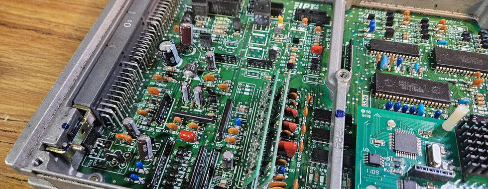


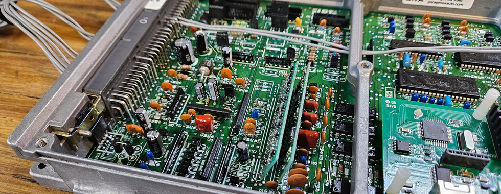


Photos by Chris - Garage Noir Auto
This change made a huge impact, stabilizing the voltage to the ECU enough that, with the combination of the new ground and battery cables, eliminated the majority of issues we had experienced. This change also fixed the issue of the alternator output voltage jumping around erratically under load, presumably as the alternator field wire signal (which comes from the ECU) was more stable as well.
This was surprisingly cheap to do, so we recommend this as a precautionary measure for anyone with an older Honda ECU, or a Hondata-equipped ECU. We plan to send our other Hondata-equipped ECU to Garage Noir Auto for a similar service as soon as we finish writing this article.
Inspect / Replace / Protect your Ignition Control Module
Those of us who rely on the OEM Honda distributor know that the Ignition Control Module inside the distributor is a common failure point on our cars. While we have yet to find a bulletproof method of preventing ICM failures, keeping the distributor cool and providing it with clean, constant power have been shown to extend the life of both your distributor and ICM.
We recommend keeping under hood temperatures down by venting the hood (if possible), zip-tying the electrical connectors to the distributor to prevent loosening / vibration, and taking as many measures possible to ensure that the distributor receives a good, clean 12v signal when the car is running.
Or, if possible (and allowed by your rulebook), install a Coil on Plug conversion kit.
Check Your Coil Packs - And Check How They are Powered
Ignition Coils draw significantly more power than advertised and produce a tremendous amount of electrical noise and interference that will affect surrounding electronics. Because of this, they can also cause other components on the same circuit to behave erratically when they begin to fail.
We recommend taking your coil packs to an auto parts store to be inspected on an ignition coil tester. The $25 handheld coil pack inspectors from Amazon are not sensitive enough to detect a failing coil pack that is still able to produce a spark.
More importantly, we recommend that you power the coil packs from a 12v power source that connects to the battery, with no other components on the same circuit, and protect them with a 15A fuse.
Many off the shelf COP kits (and aftermarket racing harnesses) tie the power to the ECU with the power wire to the ignition coils, which allows the noise and high draw of the coil packs to feed directly back into the ECU and other engine sensors. This can cause intermittent Check Engine Light codes, idle issues, and even alternator charging issues (all of which we were experiencing on our car).
By wiring the coil packs directly to the battery, you take advantage of the fact that the battery acts like a giant capacitor, allowing it to damp out the voltage spikes and dips generated by the coil packs, thus isolating the rest of your car's electrical system from the ignition coils themselves.

Coil packs also draw a surprisingly high number of amps under load. If your coil packs are connected to a power source with a 10A fuse, you may notice that the fuse will sometimes blow under heavy load. If you experience this issue after installing a COP conversion kit, we recommend re-wiring your power source to draw from the fuse box directly, and using a 15A fuse instead. Do not replace your existing 10A fuses with 15A fuses, as this risks damage to the other components (and ECU) that are on that circuit.
The one downside to wiring the coil packs straight to the battery is that they can cause a parasitic draw on the battery when the car is off. This is very easy to address on a race or track car with a kill switch, as you can simply shut off the kill switch to disconnect the battery from the car when it is not in use. On street cars, we recommend finding an unused 15A circuit that is tied to the ignition switch, setting up a relay to disconnect the circuit when the ignition is off, or installing a switch that allows you to manually disconnect the coils.
The last option is also quite effective as an anti-theft device for modified cars, as very few potential thieves are interested enough to diagnose an ignition issue in a street car.
Replace your Main Relay
Main relay failures are a common cause of intermittent fuel, ignition, and non-starting issues. Unfortunately, even the expensive Genuine OEM Honda relay is still prone to failure due to a fundamental issue with the design of the circuit board.
Our recommendation is to replace the main relay entirely with a main relay conversion, such as the one sold by Jordan Distributors Inc. This plug-and-play kit replaces the problematic main relay with a standard Bosch-style 5-pin relay, which is much more reliable (and cheaper to replace). JDi also sells a two-relay version which maintains the separate ground and trigger wire connections in the stock relay. While this does not seem to be necessary for most street, track, and race cars, it may offer peace of mind for those of us with higher power cars or with more load on our electrical systems.
Inspect / Replace your Kill Switch
This is something that racers often forget about - Kill switches are wear items. Every time you flick that big, spring loaded lever, you wear the terminals on the inside of your weather-resistant kill switch. It is worth testing the resistance across the poles of the kill switch while it is in the On position, to ensure that you see 0 Ohms of resistance.
Our 8 year old Longacre kill switch showed a noticeable amount of resistance (5 Ohms!) across the secondary poles, which we use to disconnect the alternator field wire. We replaced our kill switch before it could cause additional wear and tear on our alternator.

Step 5 - Helpful Add-ons
In addition to the above, there are some affordable add-ons that can help mitigate voltage instability and other electrical issues. Of all of the items we tested, there are two in particular that were helpful for solving issues with voltage instability and signal interference:
DC 12v Voltage Regulators
Also known as DC-DC Buck-Boost Controllers, these small boxes can stabilize the voltage from automotive power sources, absorb surges, and maintain a steady 12v to critical components in your car, such as your ECU and Ignition Control Module.

After testing multiple brands, we found that this EKYLIN brand stabilizer worked the best and had the fewest reported failure rates of all of the compact and affordable options on the market today. Just wire the 12v in and 12v out power leads inline with the circuit that you want to stabilize, and connect the ground wires to two separate locations where you can get a known good ground (preferably to the chassis).
These voltage regulators can be used as a band-aid to get you through a dyno tuning session or race weekend, but can also be used as surge protectors for sensitive circuits. We left ours connected to the 12v power wire for our engine harness to ensure that the most sensitive components get steady and clean power under the unforgiving conditions of the racetrack.
Ferrite Beads for Protection against Electromagnetic Interference
This one is more important for street cars with sensitive in-car electronics (such as sound systems, GPS, and in-car entertainment screens) than race cars. Clip-on ferrite beads can go a long way towards suppressing interference from noisy electronics in the vicinity of your sensitive components.
These are commonly used to eliminate buzzing and static on sound systems and monitor cables. Having used them on street cars and computer equipment, we can say with confidence that they do work. They will also reduce the amount of noise emitted by noisy electronics, such as coil packs or the thick wire connecting the ignition coil to the distributor on external coil ignition systems.

We recommend attaching the beads about 2 inches, or about 5 cm, from the device you want to protect or the device producing the EMI. While this did not solve our erratic voltage problem, it did eliminate the obnoxious buzzing from our 5V DC power adapter as well as the USB connection that powers our in-car cameras. We also tried these on the jumper harness of our in-car radios and found that the radios picked up less static and odd noises when the car was running. If you have enough cable length and the wires are thin enough, we recommend looping the cable around so that the bead clamps over two or even three runs of wire.
Considering how cheap these beads are, they are worth trying, especially on anything that transmits sound or video.
A Few Final Words of Advice
In the end, it was a combination of re-grounding the car with new wires, repairing the ECU, and separating the ignition coils from the rest of the car's 12v power system that eliminated our intermittent electrical issues once and for all. This was a frustrating and time-consuming exercise for us here at StudioVRM, due in no small part due to the decision to test multiple methods and products (many of which did not work as stated).
But having spent months combing through the electrical system before seeing the car perform on track with zero electrical issues, we can say with confidence that this was time and money well spent.
Our recommendation is to work slowly and methodically, over days and weeks if necessary, while taking careful notes as to what you found and fixed. Intermittent electrical issues may seem daunting at first, but they are all very solvable - and the tools / parts to fix them are more affordable now than ever.
Just remember - these cars are not that complicated. You can do this.
See you at the track.
Disclosure:
StudioVRM and Roger Maeda are not affiliated with Steel Camel, CLM Motorsports, DeoxIT, Summit Racing, Garage Noir Auto, JDI, Astro Tools, or any of the other vendors mentioned here. Any of the parts purchased and reviewed for this article have been purchased at full price from our team's car development budget and Roger's own pocket.
StudioVRM is an Amazon Associate, which means that we get a small amount of referral income if you buy a product using any Amazon links in the article.


